I consider the next project important because it is an attempt to improve the human-machine interface towards something more dynamic. I can actually imagine screens everywhere around me, on the walls, desks, tales, floating around…. and everything is in control with this device and I can move and go anywhere with it. Nydeum sense.
Tag Archives: keyboard
Arduino Micro + A-star 32U4 Micro + RF link (434 MHz)
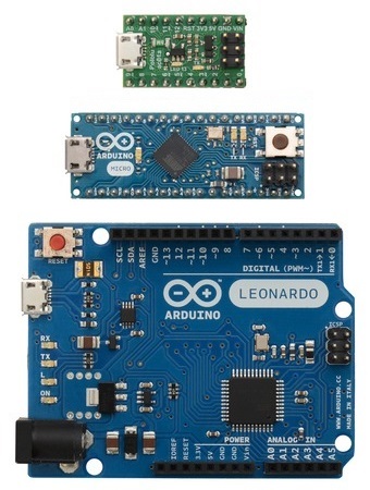
Today I want to play with the small Arduino Micro and the even smaller A-Star 32U4 Micro. You can see how small they are when compared with the more familiar Arduino Leonardo.
Why to use these 2? The main reason for using the A-Star 32U4 is because it is small, so small that it is ideal for placing it inside a toy or a wearable. The second reason is because it is Arduino compatible (means that it can be programmed using the Arduino IDE). The main reason for using the Arduino Micro is because when connected to the computer by USB, the computer can see it as a Keyboard + Mouse, hence you can use it to simulate keyboard or mouse input.
So today the tutorial will be:
- Setting up the A-Star with the “Blink LED” example.
- Simulate keyboard with Arduino Micro.
- RF link between A-Star and Arduino Micro to simulate a wireless keyboard.
Components I’m going to use:
- A-Star 32Ua
- Arduino Micro
- 7 Segment LED display
- Lithium Polymer battery
- LiPo Micro-USB charger
- 5V Step-up/Step-Down voltage regulator
- RF Link (434 MHz) Transmitter and Receiver
- Breadboard (depending on how tidy you are, you can use more or lees of these)
- Button
As many other times, components where provided by Coolcomponents.

So, lets start by setting up the A-Star.
The complete guide is provided by Pololu here.
- Download the A-Star Software and Drivers (alternatively can be found on GitHub) and extract the ZIP file.
- Inside the “drivers” folder, rigth-click in “a-star.inf” and select install. Accept any prompt.
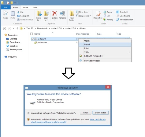
- Done! (If you are using Windows XP or other OS, then it is better to double check the guide.
- Now let’s go to the Arduino IDE. If you don’t have the Arduino IDE, download it here and install it.
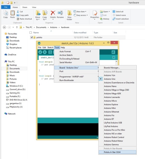
- From the A-Star software and drivers you have downloaded and unziped, locate the “add-on” folder and copy the “polulu” folder into \Arduino\hardware (typically located inside a Arduino folder in the Documents folder, if necessary, create the hardware folder).
- Restart the Arduino IDE, now it will be possible to select the A-Star 32U4 in the board list.
- First program. For programming you can use the same commands as with Arduino (taking into account the different number of pins and properties of pins). So if you want, you can simply open an example program and load it into the board. For instance “blink” will turn on and off the board LED in pin 13 (as with Arduino). This will confirm that drivers are ok. Note: Make sure board and port are correct. In our case, we are going to do a more complex program, we want a program that displays in a 7 segment LED the number of times we have pressed a button (after 10 times goes back to zero).
- The circuit diagram is shown here. The battery is connected to the LiPo charger (charge the battery before connecting it to a USB port), and the output is connected to the 5V voltage regulator. After loading the program into the board, we can disconnect the USB cable and power the board using the LiPO (the reason of doing it this way instead of using the VIN is because the micro USB requires 5V as the output of the voltage regulator, while VIN requires at least 5.5V to work properly).
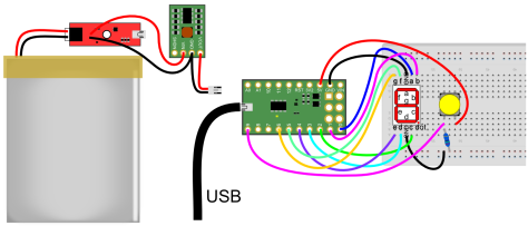 On the other side of the circuit, the A-Star is connected to the 7 segment LED (connect ground and 6 digital pins and pay attention to the order of the connections). The last thing to connect is the push-button. The button is connected to 5V in one side and to digital pin 9 and through a resistor to ground in the other side. In this way, every time we push the button pin 9 goes to 5V (without draining too much current) and when released, pin 9 goes back to GND.
 - Now the code. Basically, we will be reading the button state and counting the number of times it is pressed. The LED will display the number of times we have pressed the button.
int num = 0; int previousnum =0; boolean state = false;void setup() { //Initialize pins to be used as outputs pinMode(0, OUTPUT); pinMode(1, OUTPUT); pinMode(2, OUTPUT); pinMode(3, OUTPUT); pinMode(4, OUTPUT); pinMode(5, OUTPUT); pinMode(6, OUTPUT); //Initialize pin 9 to read the pushbutton state pinMode(9, INPUT); }void loop() { delay(10); //In each iteration of the loop we check the status of the button. //If status is false, it means that we just pressed the button, then number goes up and the state goes to true //by changing the state to true, we make sure we count only one each time the button is being pressed. //State goes back to false only if the button is depressed. //then state goes into true if (state == false and digitalRead(9) == HIGH){ state= true; num=num+1; } if (digitalRead(9) == LOW){ state= false; }//If the number of times the button has been pressed increases, then we need to change the displayed number if (previousnum == num){ } else{ previousnum=num; switch (num) { //Depending on the number that needs to be displayed, we turn on a set of LEDs or other case 0: //Each time we start by reseting all LEDs to low clean(); digitalWrite(0, HIGH); digitalWrite(1, HIGH); digitalWrite(2, HIGH); digitalWrite(3, HIGH); digitalWrite(4, HIGH); digitalWrite(5, HIGH); break; case 1: clean(); digitalWrite(1, HIGH); digitalWrite(2, HIGH); break; case 2: clean(); digitalWrite(0, HIGH); digitalWrite(1, HIGH); digitalWrite(4, HIGH); digitalWrite(3, HIGH); digitalWrite(6, HIGH); break; case 3: clean(); digitalWrite(0, HIGH); digitalWrite(1, HIGH); digitalWrite(2, HIGH); digitalWrite(3, HIGH); digitalWrite(6, HIGH); break; case 4: clean(); digitalWrite(1, HIGH); digitalWrite(2, HIGH); digitalWrite(5, HIGH); digitalWrite(6, HIGH); break; case 5: clean(); digitalWrite(0, HIGH); digitalWrite(5, HIGH); digitalWrite(6, HIGH); digitalWrite(2, HIGH); digitalWrite(3, HIGH); break; case 6: clean(); digitalWrite(0, HIGH); digitalWrite(5, HIGH); digitalWrite(6, HIGH); digitalWrite(2, HIGH); digitalWrite(3, HIGH); digitalWrite(4, HIGH); break; case 7: clean(); digitalWrite(1, HIGH); digitalWrite(2, HIGH); digitalWrite(0, HIGH); break; case 8: clean(); digitalWrite(0, HIGH); digitalWrite(1, HIGH); digitalWrite(2, HIGH); digitalWrite(3, HIGH); digitalWrite(4, HIGH); digitalWrite(5, HIGH); digitalWrite(6, HIGH); break; case 9: clean(); digitalWrite(0, HIGH); digitalWrite(5, HIGH); digitalWrite(2, HIGH); digitalWrite(6, HIGH); digitalWrite(1, HIGH); break; default: clean(); num = 0; break; } //This just limit the values num can take between 0 and 9 if (num >= 10) { num = 0; } } }//This is the function that resets the LEDs to low void clean() { digitalWrite(0, LOW); digitalWrite(1, LOW); digitalWrite(2, LOW); digitalWrite(3, LOW); digitalWrite(4, LOW); digitalWrite(5, LOW); digitalWrite(6, LOW); } - Upload the code, connect the battery and it is done!
Now let’s simulate a keyboard key press with the Arduino Micro.
- The circuit diagram for this is very simple, just the Arduino and a push-button (the one we used in the previous example for instance).
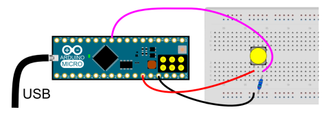
- The code is very simple, just read the state of the bottom and the function Keyboard.write() will do the rest.
boolean state = false; void setup() { // initialize the buttons' inputs: pinMode(5, INPUT); // initialize mouse and keyboard control: Mouse.begin(); Keyboard.begin(); }void loop() { delay(2); //If the buttom is pressed, then we write letter u if (state == false and digitalRead(5) == HIGH) { state = true; Keyboard.write('u'); //as an example, to move the mouse up 40 units the command is Mouse.move(0, -40); } if (digitalRead(5) == LOW) { state = false; } } - Done! Note:You will need to install Arduino Micro drivers before the computer recognises it as a keyboard.
Now it is time to set up the RF link between A-Star and the Arduino Micro. To do so, we are going to re-use most of what we learnt with the
Arduino +RF Link Transmitter/Receiver (434MHz) + ZUMO shield
So, if you miss something, go there and check the steps.
- In the previous tutorial, we uncommented a line of code inside RH_ASK.cpp it needs to be commented again, because now we can use the timmer1 (in fact, it will give an error if not commented).
- This is the wiring for the receiver.
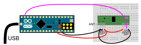 Simply power the RF receiver and connect the first data line to pin 11. As an extra, you can add a wire to the antenna, for 434 MHz 16.5 cm wire will do it ok as a quarter wavelength antena.
 - The code is mainly taken from the previous tutorial. Here you might want to add or change more cases or in some cases enable mouse control.
#include <RH_ASK.h> #include <SPI.h> // Not actualy used but needed to compile //Enable timmer2 instead of timmer1 #define RH_ASK_ARDUINO_USE_TIMER2 RH_ASK driver(2000, 11, 12, 13, false);;float Sensor1Data; char Sensor1CharMsg[4];//This is the message passed by the emitter. If you need to pass more data, simply make it bigger.void setup() { Keyboard.begin(); //For some reason, this is needed to initialize the driver. if (!driver.init()) { Serial.println("init failed"); } }void loop() { ////////////////This piece of code is just for reading the RF signal uint8_t buf[RH_ASK_MAX_MESSAGE_LEN]; uint8_t buflen = sizeof(buf); if (driver.recv(buf, &buflen)) // Non-blocking { int i; // Message with a good checksum received, dump it. for (i = 0; i < buflen; i++) { // Fill Sensor1CharMsg Char array with corresponding // chars from buffer. Sensor1CharMsg[i] = char(buf[i]); } // Null terminate the char array // This needs to be done otherwise problems will occur // when the incoming messages has less digits than the // one before. Sensor1CharMsg[buflen] = '\0'; // Convert Sensor1CharMsg Char array to integer Sensor1Data = atof(Sensor1CharMsg); ///////////////////The next piece of code is what changes what to do depending on the button pulsed //Choose the correct speeds depending on the command if (Sensor1CharMsg[0] == 'f') { Keyboard.write('w'); } if (Sensor1CharMsg[0] == 'b') { Keyboard.write('s'); } //Un comment this code if you want to send data from more than one button // if (Sensor1CharMsg[1] == 'l') { //Keyboard.write('l'); // } } } - The next diagram is the emitter.
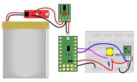 Basically it is the S-Star connected to a button, the emitter, and powered by the battery.
 - The code for the emitter reads the button state and sends the signal to the receiver.
#include <RH_ASK.h> #include <SPI.h>// Not actually used but needed to compile RH_ASK driver; boolean state = false; void setup() { // initialize the buttons' inputs: pinMode(11, INPUT);//For some reason, this is needed to initialize the driver. if (!driver.init()) { Serial.println("init failed"); } }void loop() { char msg[8]; if (state == false and digitalRead(11) == HIGH) { state = true; msg[0] = 'f'; //as an example, to move the mouse up 40 units the command is Mouse.move(0, -40); } if (digitalRead(11) == LOW) { state = false; msg[0] = 'b'; } //If you want or need to send more data from anotter button, use something like msg[1]='n'; //Send the message and wait to check if it was sent. driver.send((uint8_t *)msg, strlen(msg)); driver.waitPacketSent(); //Flsh the LED on pin 13 to indicate that the board is working. digitalWrite(13, 1); delay(20); digitalWrite(13, 0); delay(20); } - Done! You are ready to roll and make your own wireless controllers!
Stay tuned because the next tutorial will be implementing this inside an old NES controller.
