Today M.E. (Mysterious Explorer) send to me this.
Tag Archives: love
Jurassic Park vs Jurassic World
The next video captures the essence of Jurassic Park and perfectly explains why the new movie born without a heart (as so many movies these days).
ASFOW
Today M.E. (Mysterious Explorer) send to me this.
The walk of life project
The walk of life project is a project to change the final song of movies based in the next hypothesis: “walk of life” by dire straits is the perfect song to end any movie. Do you agree?
the GaMERCat


ASFoW
Today M.E. (Mysterious Explorer) send to me this.
Darth Vader | Robot Chicken
Masahiro Ichikawa. Origami flowers.
One thing pops to my head over and over when I see this origami master in action… Valentine’s gift.
Kyoto rules
Kyoto city is visited every year for so many tourists that they have created this infographic in order to help them to behave in public places and in social events.


Arduino +RF Link Transmitter/Receiver (434MHz) + ZUMO shield
A few months ago I create some tutorials about how to use Arduino and the XBee to do radio-frequency.
Python + Arduino + XBee + Zumo robot
XBee 002: radio-chat between PC and Arduino
XBee 001 Basic example: radio-chat between 2 PC
Today I’m going to show you how to do it with the cheap RF link modules.
So, first of all, thanks to Coolcomponents for providing an excellent customer service (basically, even if you order one or two components, they deliver within one or two days at a very low extra cost).
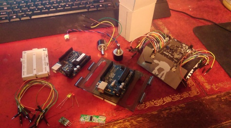
 Second, materials. I’m reusing 2 Arduino boards (Duemilanove with chip Atmega 328, and UNO), and the Zumo robot from previous post, plus 2 LEDs, one potentiometer, a few wires, one battery (not in the picture), a small cardboard box, and the RF modules (which I bought from Coolcomponents):
RF Link Receiver – 4800bps (434MHz)
Before starting the main project, let’s do a warm up with a basic example on how to work with these RF modules.
Introduction project.
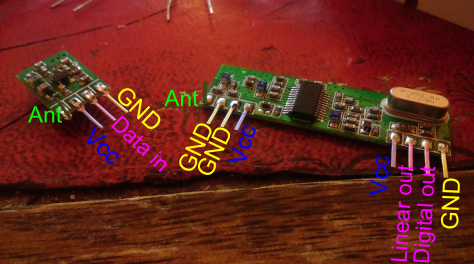
We start by naming the connectors in the RF link modules (spreadsheet for receiver / transmitter). It is good to bend the antenna pins, otherwise when using a breadboard they will be inserted into the breadboard connectors and result in range reduction.
Now for the circuit. We basically read an analog value from the variable resistor on the Duemilanove board, transmit it using the RF transmitter to the RF receiver connected to the UNO board, and light red/yellow LED depending on the value.
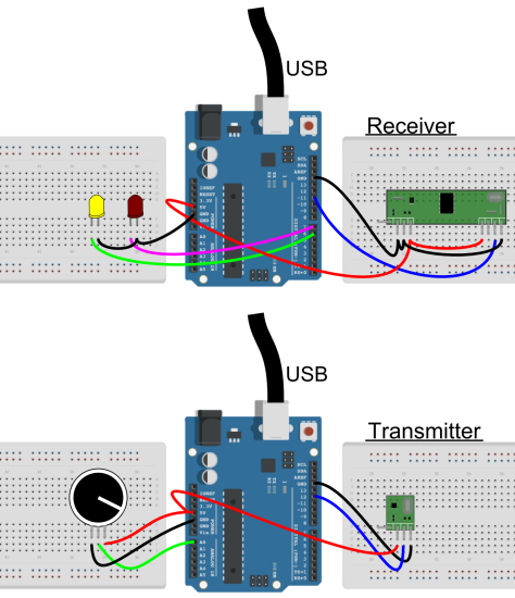
The value of the resistor in the potentiometer is not important as we will convert it to a value between 0 and 5V. For the LEDs, as they are standard ones, it is OK to attach them to digital outputs.
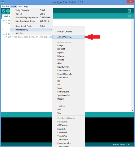
The next step is the code. In order to achieve a good signal (these modules has a lot of noise), we need to get the RadioHead library (Originally it was VirtualWire, but it has been discontinued and now RadioHead is the one being used). You can download the last version, from here. (If you wonder how to connect these circuits to the Arduino, look at the “Detailed description here).
Once you have it, add it to the Arduino IDE.
Once the library is added to the Arduino library list, everything is ready to upload the code. Here it is the code for the transmitter.
// Modified version of ask_transmitter.pde by RadioHead
// -*- mode: C++ -*-
// Simple example of how to use RadioHead to transmit messages
// with a simple ASK transmitter in a very simple way.
// Implements a simplex (one-way) transmitter with an TX-C1 module
#include <RH_ASK.h>
#include <SPI.h> // Not actually used but needed to compile
RH_ASK driver;

void setup()
{
  //LED indicates message sent.
  pinMode(13,OUTPUT);
  Serial.begin(9600);
  //For some reason, this is needed to initialize the driver
  if (!driver.init())
  {
    Serial.println("init failed");
  }
}

void loop()
{
  char msg[4];
  //Read the voltage in the potentiometer.
  float voltage= analogRead(0)* (5.0 / 1023.0);
  //Convert it to string
  dtostrf(voltage,1,1,msg);

  //Send the message and wait to check if it was sent.
  driver.send((uint8_t *)msg, strlen(msg));
  driver.waitPacketSent();

  //Flash LED to indicate message sent.
  digitalWrite(13,1);
  delay(200);
  digitalWrite(13,0);
  delay(200);
}
This is for the receiver.
//  Modified version of ask_receiver.pde by RadioHead
// -*- mode: C++ -*-
// Simple example of how to use RadioHead to receive messages
// with a simple ASK transmitter in a very simple way.
// Implements a simplex (one-way) receiver with an Rx-B1 module
#include <RH_ASK.h>
#include <SPI.h> // Not actualy used but needed to compile
RH_ASK driver;
float Sensor1Data;
char Sensor1CharMsg[4];
void setup()
{
  //LED indicates message sent.
  pinMode(13, OUTPUT);
  Serial.begin(9600); // Debugging only.
  //For some reason, this is needed to initialize the driver.
  if (!driver.init()) {
    Serial.println("init failed");
  }
  //These are for the LEDs
  pinMode(5, OUTPUT);
  pinMode(6, OUTPUT);

}
void loop()
{
  uint8_t buf[RH_ASK_MAX_MESSAGE_LEN];
  uint8_t buflen = sizeof(buf);
  if (driver.recv(buf, &buflen)) // Non-blocking
  {
    int i;
    // Message with a good checksum received, dump it.
    for (i = 0; i < buflen; i++) { // Fill Sensor1CharMsg Char array with corresponding // chars from buffer. Sensor1CharMsg[i] = char(buf[i]); } // Null terminate the char array // This needs to be done otherwise problems will occur // when the incoming messages has less digits than the // one before. Sensor1CharMsg[buflen] = '\0'; // Convert Sensor1CharMsg Char array to integer Sensor1Data = atof(Sensor1CharMsg); //Turn on the corresponding LED if (Sensor1Data > 3) {
      digitalWrite(5, HIGH);
      digitalWrite(6, LOW);
    }
    if (Sensor1Data < 2) {

      digitalWrite(5, LOW);
      digitalWrite(6, HIGH);
    }

    //Flash to indicate message received.
    digitalWrite(13, 1);
    delay(200);
    digitalWrite(13, 0);
    delay(200);
  }
}
And Voilà! With this you are able to light the red or the yellow LED just by adjusting the potentiometer.
This very basic example can be used to transmit a signal form a sensor, to do some wireless projects, or for isntance, to control a device like the ZUMO shield.
RF-link and the ZUMO.
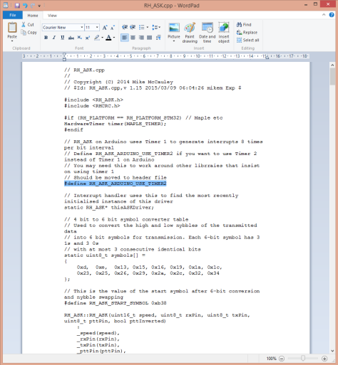
First important thing. The ZUMO shield uses most of the timers in the Arduino board, in particular, the timer1 which is also required for the RadioHead library. So, we need to change the RadioHead library to use timer2. In order to do so, we need to edit the RadioHead library. Simply look for the library and open …Documents\Arduino\libraries\RadioHead\RH_ASK.cpp using a text editor. You need to uncomment //#define RH_ASK_ARDUINO_USE_TIMER2
This line should be also added into your Arduino code for the receiver.
The circuits for the new project can be seen below. Basically, instead of reading one analog value, we are now reading 2, one for forward/backwards control, and the other for turning left/right. The second Arduino just sits on top of the ZUMO shield and uses a couple of wires to connect to the RF receiver.

The code for the new transmitter is
// Modified version of ask_transmitter.pde by RadioHead
// -*- mode: C++ -*-
// Simple example of how to use RadioHead to transmit messages
// with a simple ASK transmitter in a very simple way.
// Implements a simplex (one-way) transmitter with an TX-C1 module
#include <RH_ASK.h>
#include <SPI.h> // Not actually used but needed to compile
RH_ASK driver;

void setup()
{
  //LED indicates message sent.
  pinMode(13, OUTPUT);
  Serial.begin(9600);
  //For some reason, this is needed to initialize the driver.
  if (!driver.init())
  {
    Serial.println("init failed");
  }
}

void loop()
{
  char msg[8];
  //Read the voltage in the potentiometer.
  //This one encodes forward/neutral/backwards
  float voltage1 = analogRead(0) * (5.0 / 1023.0);
  //Read the voltage in the potentiometer.
  //This one encodes left/neutral/rigth
  float voltage2 = analogRead(1) * (5.0 / 1023.0);
  if (voltage1 > 2.6) {
    msg[0] = 'f';
  } else if (voltage1 < 2.4) { msg[0] = 'b'; } else { msg[0] = 'n'; } if (voltage2 > 2.6) {

    msg[1] = 'r';
  } else if (voltage2 < 2.4) {
    msg[1] = 'l';
  }
  else {
    msg[1] = 'n';
  }

  //Send the message and wait to check if it was sent.
  driver.send((uint8_t *)msg, strlen(msg));
  driver.waitPacketSent();

  //Flash LED to indicate message sent.
  digitalWrite(13, 1);
  delay(20);
  digitalWrite(13, 0);
  delay(20);
}
This time, just to make this example more general, we transmit characters. F for forward, b for backwards, n for neutral, l for left and r for right. The code for the receiver is
//  Modified version of ask_receiver.pde by RadioHead
// -*- mode: C++ -*-
// Simple example of how to use RadioHead to receive messages
// with a simple ASK transmitter in a very simple way.
// Implements a simplex (one-way) receiver with an Rx-B1 module
#include <RH_ASK.h>
#include <SPI.h> // Not actualy used but needed to compile
//Enable timmer2 instead of timmer1
#define RH_ASK_ARDUINO_USE_TIMER2
RH_ASK driver(2000, 11, 12, 13, false);;
#include <ZumoMotors.h>
ZumoMotors motors;
float Sensor1Data;
char Sensor1CharMsg[4];
int left_speed, right_speed;
void setup()
{
  //LED indicates message sent.
  pinMode(13, OUTPUT);
  Serial.begin(9600); // Debugging only.
  //For some reason, this is needed to initialize the driver.
  if (!driver.init()) {
    Serial.println("init failed");
  }
}
void loop()
{
  uint8_t buf[RH_ASK_MAX_MESSAGE_LEN];
  uint8_t buflen = sizeof(buf);
  if (driver.recv(buf, &buflen)) // Non-blocking
  {
    int i;
    // Message with a good checksum received, dump it.
    for (i = 0; i < buflen; i++)
    {
      // Fill Sensor1CharMsg Char array with corresponding
      // chars from buffer.
      Sensor1CharMsg[i] = char(buf[i]);
    }
    // Null terminate the char array
    // This needs to be done otherwise problems will occur
    // when the incoming messages has less digits than the
    // one before.
    Sensor1CharMsg[buflen] = '\0';
    // Convert Sensor1CharMsg Char array to integer
    Sensor1Data = atof(Sensor1CharMsg);

    //Choose the correct speeds depending on the command
    if (Sensor1CharMsg[0] == 'f') {
      left_speed = 200;
      right_speed = 200;
    }
    if (Sensor1CharMsg[0] == 'b') {
      left_speed = -200;
      right_speed = -200;
    }
    if (Sensor1CharMsg[0] == 'n') {
      left_speed = 0;
      right_speed = 0;
    }
    if (Sensor1CharMsg[1] == 'l') {
      left_speed = left_speed + 100;
      right_speed = right_speed - 100;
    }
    if (Sensor1CharMsg[1] == 'r') {
      left_speed = left_speed - 100;
      right_speed = right_speed + 100;
    }
    if (Sensor1CharMsg[1] == 'n') {
      left_speed = left_speed;
      right_speed = right_speed;
    }

    //Activate motors
    ZumoMotors::setSpeeds(left_speed, right_speed);

    //Flash to indicate message received.
    digitalWrite(13, 1);
    delay(200);
    digitalWrite(13, 0);
    delay(200);

  }
}
Now it is a matter of uploading the code to the Arduinos and pack things inside the cardboard box…
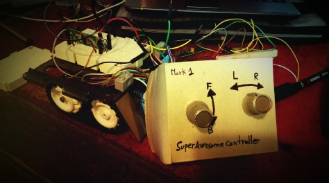
…and you are ready to have some fun with the ZUMO shield.
Compared with the XBee the range is not great, but these modules are by far cheaper than the XBee, and they can be improved by adding antennas.
