The next sensor will be a must-have in all your electronics projects. Basically it uses light to detect obstacles. Imagine vacuum cleaners, pet-robots, drones, presence detectors… even gesture recognition. Say welcome to sweep.
Today I’m building a light for my bike’s wheel. This light will be attached to the wheel and will shine on and off as the wheel spins in order to create a stand still image.
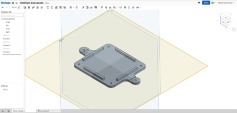
Usually I build things just buying electronics and putting them together, but for this one I need an extra step, design and fabrication of a plastic box to attach the light to the wheel. Because of this extra step, I though this was a nice opportunity to try 4 Delta 3D printing training course.
Although I have used 3D printing before (see for instance my light stand or how I fixed an old game), I lack most of the good practice in 3D printing knowledge, and the 4 Delta course covers that perfectly.
The course is completely on-line with videos and e-books. It took me about one week working only half an hour or less everyday. Within the course, you learn how to properly design pieces, the materials available, how to set-up your 3D printer, common design mistakes, how to export models, printing errors… and you get access to Onshape (CAD software that runs on your browser). And if it was not enough, for your cash… you get permanent access to the new 4 Delta forum where you can ask and solve questions about DIY 3D printing. Resuming, it is a very good investment in yourself and your future projects.
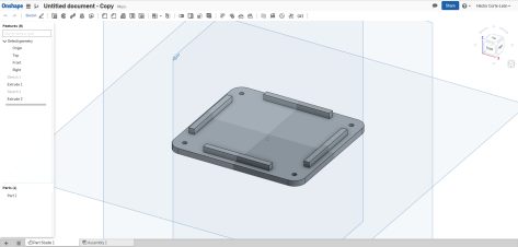
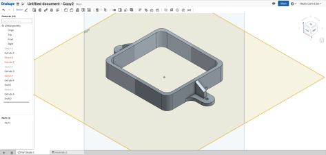
So… I took the course and used Onshape to design my box.
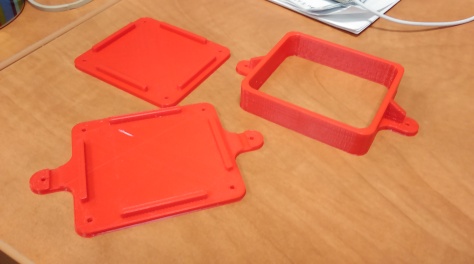
It was composed of 3 parts.
And it includes holes for attaching the parts together with screws.
The idea is that the last piece and the middle one will grip on the wheel radios fixing the box in place. However, although this design is made in order to make 3D printing easy, it has some defects that can be improved. For instance, walls of the middle part are too thick and don’t include wholes for connecting USB, there is no holes for attaching the lights or the electronics, the box should be able to attach/detach from the bike without having to open them completely (this feature will need a major review), and there is no mounting for the Hall sensor that will determine the angular position.
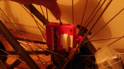
However, for a Mark 1 model the design is good enough and this is how it looks like once 3D printed (I used 4Delta printers through the 3D HUBS).
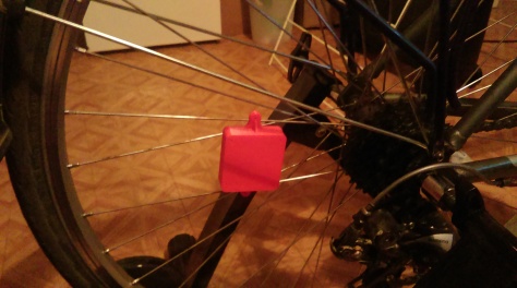
and this how it goes on my bike (I have a stand to workout at home during winter).
Now lets go for the electronics.
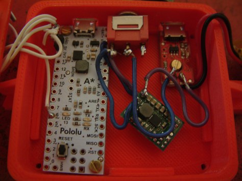
Recently I have used a very nice A-Star micro board (because it is extremely tiny). For this project I will be used the bigger version, the A-Star micro. Why going for the A-Star instead of one of the more common and better supported Arduino boards? My main reason is because they do the A-Star micro and hell, that board is really tinny. By using more boards from the same company, I will be able to learn more and improve my designs even further.
Linear Hall sensor (this one in particular is quite expensive and not all its features are used here, but I found that it is a quite good sensor so I keep using it as much as I can).
Neodymium magnet (I use an old one from a hard drive, but any magnet can do)
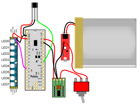
The circuit diagram for this set-up is quite simple. Note: If using more NeoPixel sticks, they can be attached in series one after the other.
The circuit diagram is a battery attached to a micro-USB for charging. The output of the battery is attached to an interrupter which output goes to the voltage regulator. The voltage regulator powers the A-Star. The A-Star powers both the Hall sensor and the NeoPixel LED strip. The output of the Hall sensor is connected to the analogue pin A5 (pin 23) and the input of the NeoPixel is attached to pin 6.
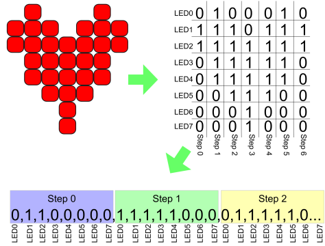
Now lets go for the code, but before explaining the code, 2 things. The first one is that in order to run the NeoPixel, you need to download the zip file with the libraries and install it in the Arduino IDE (simply Sketch>Include Library>Add .ZIP Library). The second thing is about how to draw things. For my example I’m going to use a red heart. The idea is that the shape we want to draw is divided into columns, each one of 8 rows. As the wheel spins the LEDs will cycle through the columns. So we can turn our draw into an array and know exactly which pixel has to be on and when. In addition, as the NeoPixel LEDs are numbered we need to convert the array into a vector and cycle through the vector.
Keeping this in mind, this is the code I prepared. Basically, it reads the Hall sensor and when the signal from the sensor deviates from the average it means the sensor has passed over the magnet and a turn of the wheel has happened. With this trick we can measure the period of a revolution and hence synchronize the lighting of LEDs. The next thing that the code does is light the LEDs according tot he pattern (see heart shaped pattern above), the time it takes to jump from one step to another depends on the speed of the wheel (right now it is set to take about 1 degree).
#include <Adafruit_NeoPixel.h>
#ifdef __AVR__
#include <avr/power.h>
#endif

// Which pin on the Arduino is connected to the NeoPixels?
#define PIN            6

// How many NeoPixels are attached to the Arduino?
#define NUMPIXELS      8
//This is to define the shape we want to draw (Note: monocolor at the moment).
int pixi[] = {0, 1, 1, 0, 0, 0, 0, 0, 1, 1, 1, 1, 1, 0, 0, 0, 0, 1, 1, 1, 1, 1, 0, 0, 0, 0, 1, 1, 1, 1, 1, 1, 0, 1, 1, 1, 1, 1, 0, 0, 1, 1, 1, 1, 1, 0, 0, 0, 0, 1, 1, 0, 0, 0, 0, 0,0,0,0,0,0,0,0,0};
//This defines the number of steps it takes to draw the full image
int numsteps = 7;

//This is to measure position using the Hall sensor
#define numReadings 20
float readings[numReadings];
float sensorval;
float average = 0;
int start;
int finished;

// When we setup the NeoPixel library, we tell it how many pixels, and which pin to use to send signals.
// Note that for older NeoPixel strips you might need to change the third parameter--see the strandtest
// example for more information on possible values.
Adafruit_NeoPixel pixels = Adafruit_NeoPixel(NUMPIXELS, PIN, NEO_GRB + NEO_KHZ800);

void setup() {
  pixels.begin(); // This initializes the NeoPixel library.
  start = millis(); //This initialices the function to meassure the wheel speed.
}

void loop() {
//Hall sensor is attached to pin 23
//We read the output each iteration (Powering the sensor with 5V the output is 2.5V at zero magnetic field and 0V/5V at negaqtive/positive saturation.
//At the moment we don't need to convert the reading from 1024 bits into a real voltage reading.
  sensorval = analogRead(23);
//We keep the last 20 values in memory by sifting values in an array
//and simply deleting the oldest one and adding the new one at the beguining
//To save time the average is calculated at the same time
  average = readings[numReadings-1];
  for (int k = 1; k < numReadings; k++)   {     readings[numReadings - k] = readings[numReadings - 1 - k];     average = average + readings[numReadings - k];   }   average = average / numReadings;   readings[0] = sensorval;   //Now, if the new reading deviates too much from the average (standard deviation can be calculated,    //but symply by using a fixed interval works fine), then it means the wheel has completed a cycle and it is time to draw again the symbol.   //We can use the elapsed time to calculate the spinning speed. //An artificial delay can be included here to select in which part of the cycle we want to draw.   if (sensorval > average + 20 or sensorval < average - 20)
  {
    finished = millis();
float milisperangle = abs(finished - start) / 360;
start = millis();
delay(milisperangle*8);
draw(3*milisperangle);
  }
}

void draw(int delayval)
{
  //This function takes numteps x delayval (ms) to execute
  //For a set of NeoPixels the first NeoPixel is 0, second is 1, all the way up to the count of pixels minus one.
  for (int j = 0; j < numsteps; j++) {
    for (int i = 0; i < NUMPIXELS; i++) {
      // pixels.Color takes RGB values, from 0,0,0 up to 255,255,255
      //Now we only use red color
      pixels.setPixelColor(i, pixels.Color(255 * pixi[i + j * NUMPIXELS], 0, 0)); // Moderately bright green color.
    }
    pixels.show(); // This sends the updated pixel color to the hardware.
    delay(delayval); // Delay for a period of time (in milliseconds).
  }
}
Remember that depending on which side of the wheel you place the lights the spinning is the same as you write or the opposite and you need to change the steps accordingly.
The next step is placing the components inside of the box (I added some extra wholes). Some of the wholes could have been done in the designing part, but I didn’t though too much in the final details, also, some of the wholes is better to do them afterwards in order to have a good print.
The battery goes on top and the box closes gripping to the wheel.
As I said, I didn’t include a support for the Hall sensor, so I added a last-minute solution which also allows me to change the distance between the sensor and the magnet (the thing close to the sensor in the next picture).
And Voilá!
That’s all!
.
.
.
.
.
.
.
Ok ok. Here it is, a tribute to 4 Delta for their help with the training and the 3D printing…
.
.
.
.
.
.
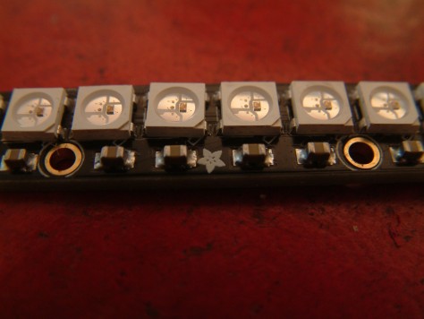
Want even more?!
As an extra, here it is a close look at the NeoPixels.
The best way to start the year is with new, greener, projects. I wish I have a garden to try this out. However, I prefer having a smaller robot and pots circulating like train wagons.
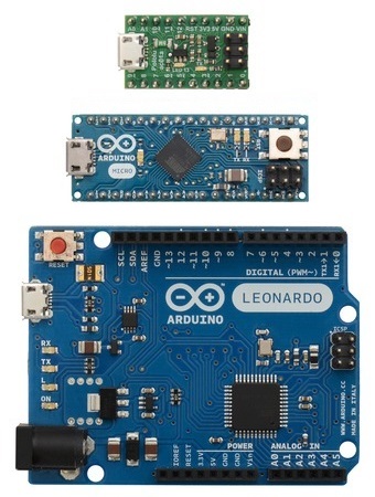
Today I want to play with the small Arduino Micro and the even smaller A-Star 32U4 Micro. You can see how small they are when compared with the more familiar Arduino Leonardo.
Why to use these 2? The main reason for using the A-Star 32U4 is because it is small, so small that it is ideal for placing it inside a toy or a wearable. The second reason is because it is Arduino compatible (means that it can be programmed using the Arduino IDE). The main reason for using the Arduino Micro is because when connected to the computer by USB, the computer can see it as a Keyboard + Mouse, hence you can use it to simulate keyboard or mouse input.
So today the tutorial will be:
Setting up the A-Star with the “Blink LED” example.
Simulate keyboard with Arduino Micro.
RF link between A-Star and Arduino Micro to simulate a wireless keyboard.
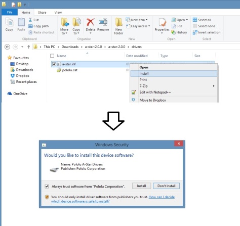
Inside the “drivers” folder, rigth-click in “a-star.inf” and select install. Accept any prompt.
Done! (If you are using Windows XP or other OS, then it is better to double check the guide.
Now let’s go to the Arduino IDE. If you don’t have the Arduino IDE, download it here and install it.
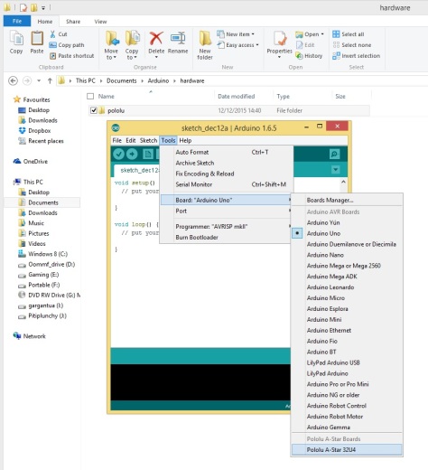
From the A-Star software and drivers you have downloaded and unziped, locate the “add-on” folder and copy the “polulu” folder into \Arduino\hardware (typically located inside a Arduino folder in the Documents folder, if necessary, create the hardware folder).
Restart the Arduino IDE, now it will be possible to select the A-Star 32U4 in the board list.
First program. For programming you can use the same commands as with Arduino (taking into account the different number of pins and properties of pins). So if you want, you can simply open an example program and load it into the board. For instance “blink” will turn on and off the board LED in pin 13 (as with Arduino). This will confirm that drivers are ok. Note: Make sure board and port are correct. In our case, we are going to do a more complex program, we want a program that displays in a 7 segment LED the number of times we have pressed a button (after 10 times goes back to zero).
The circuit diagram is shown here. The battery is connected to the LiPo charger (charge the battery before connecting it to a USB port), and the output is connected to the 5V voltage regulator. After loading the program into the board, we can disconnect the USB cable and power the board using the LiPO (the reason of doing it this way instead of using the VIN is because the micro USB requires 5V as the output of the voltage regulator, while VIN requires at least 5.5V to work properly). On the other side of the circuit, the A-Star is connected to the 7 segment LED (connect ground and 6 digital pins and pay attention to the order of the connections). The last thing to connect is the push-button. The button is connected to 5V in one side and to digital pin 9 and through a resistor to ground in the other side. In this way, every time we push the button pin 9 goes to 5V (without draining too much current) and when released, pin 9 goes back to GND.
Now the code. Basically, we will be reading the button state and counting the number of times it is pressed. The LED will display the number of times we have pressed the button.
int num = 0;
int previousnum =0;
boolean state = false;void setup() {
//Initialize pins to be used as outputs
pinMode(0, OUTPUT);
pinMode(1, OUTPUT);
pinMode(2, OUTPUT);
pinMode(3, OUTPUT);
pinMode(4, OUTPUT);
pinMode(5, OUTPUT);
pinMode(6, OUTPUT);
//Initialize pin 9 to read the pushbutton state
pinMode(9, INPUT);
}void loop() {
delay(10);
//In each iteration of the loop we check the status of the button.
//If status is false, it means that we just pressed the button, then number goes up and the state goes to true
//by changing the state to true, we make sure we count only one each time the button is being pressed.
//State goes back to false only if the button is depressed.
//then state goes into true
if (state == false and digitalRead(9) == HIGH){
state= true;
num=num+1;
}
if (digitalRead(9) == LOW){
state= false;
}//If the number of times the button has been pressed increases, then we need to change the displayed number
if (previousnum == num){
}
else{
previousnum=num;
switch (num) {
//Depending on the number that needs to be displayed, we turn on a set of LEDs or other
case 0:
//Each time we start by reseting all LEDs to low
clean();
digitalWrite(0, HIGH);
digitalWrite(1, HIGH);
digitalWrite(2, HIGH);
digitalWrite(3, HIGH);
digitalWrite(4, HIGH);
digitalWrite(5, HIGH);
break;
case 1:
clean();
digitalWrite(1, HIGH);
digitalWrite(2, HIGH);
break;
case 2:
clean();
digitalWrite(0, HIGH);
digitalWrite(1, HIGH);
digitalWrite(4, HIGH);
digitalWrite(3, HIGH);
digitalWrite(6, HIGH);
break;
case 3:
clean();
digitalWrite(0, HIGH);
digitalWrite(1, HIGH);
digitalWrite(2, HIGH);
digitalWrite(3, HIGH);
digitalWrite(6, HIGH);
break;
case 4:
clean();
digitalWrite(1, HIGH);
digitalWrite(2, HIGH);
digitalWrite(5, HIGH);
digitalWrite(6, HIGH);
break;
case 5:
clean();
digitalWrite(0, HIGH);
digitalWrite(5, HIGH);
digitalWrite(6, HIGH);
digitalWrite(2, HIGH);
digitalWrite(3, HIGH);
break;
case 6:
clean();
digitalWrite(0, HIGH);
digitalWrite(5, HIGH);
digitalWrite(6, HIGH);
digitalWrite(2, HIGH);
digitalWrite(3, HIGH);
digitalWrite(4, HIGH);
break;
case 7:
clean();
digitalWrite(1, HIGH);
digitalWrite(2, HIGH);
digitalWrite(0, HIGH);
break;
case 8:
clean();
digitalWrite(0, HIGH);
digitalWrite(1, HIGH);
digitalWrite(2, HIGH);
digitalWrite(3, HIGH);
digitalWrite(4, HIGH);
digitalWrite(5, HIGH);
digitalWrite(6, HIGH);
break;
case 9:
clean();
digitalWrite(0, HIGH);
digitalWrite(5, HIGH);
digitalWrite(2, HIGH);
digitalWrite(6, HIGH);
digitalWrite(1, HIGH);
break;
default:
clean();
num = 0;
break;
}
//This just limit the values num can take between 0 and 9
if (num &gt;= 10) {
num = 0;
}
}
}//This is the function that resets the LEDs to low
void clean() {
digitalWrite(0, LOW);
digitalWrite(1, LOW);
digitalWrite(2, LOW);
digitalWrite(3, LOW);
digitalWrite(4, LOW);
digitalWrite(5, LOW);
digitalWrite(6, LOW);
}
Upload the code, connect the battery and it is done!
Now let’s simulate a keyboard key press with the Arduino Micro.
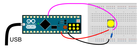
The circuit diagram for this is very simple, just the Arduino and a push-button (the one we used in the previous example for instance).
The code is very simple, just read the state of the bottom and the function Keyboard.write() will do the rest.
boolean state = false;
void setup() {
// initialize the buttons' inputs:
pinMode(5, INPUT);
// initialize mouse and keyboard control:
Mouse.begin();
Keyboard.begin();
}void loop() {
delay(2);
//If the buttom is pressed, then we write letter u
if (state == false and digitalRead(5) == HIGH) {
state = true;
Keyboard.write('u');
//as an example, to move the mouse up 40 units the command is Mouse.move(0, -40);
}
if (digitalRead(5) == LOW) {
state = false;
}
}
Done! Note:You will need to install Arduino Micro drivers before the computer recognises it as a keyboard.
Now it is time to set up the RF link between A-Star and the Arduino Micro. To do so, we are going to re-use most of what we learnt with the
So, if you miss something, go there and check the steps.
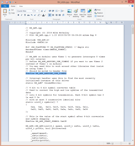
In the previous tutorial, we uncommented a line of code inside RH_ASK.cpp it needs to be commented again, because now we can use the timmer1 (in fact, it will give an error if not commented).
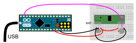
This is the wiring for the receiver.Simply power the RF receiver and connect the first data line to pin 11. As an extra, you can add a wire to the antenna, for 434 MHz 16.5 cm wire will do it ok as a quarter wavelength antena.
The code is mainly taken from the previous tutorial. Here you might want to add or change more cases or in some cases enable mouse control.
#include &lt;RH_ASK.h&gt;
#include &lt;SPI.h&gt; // Not actualy used but needed to compile
//Enable timmer2 instead of timmer1
#define RH_ASK_ARDUINO_USE_TIMER2
RH_ASK driver(2000, 11, 12, 13, false);;float Sensor1Data;
char Sensor1CharMsg[4];//This is the message passed by the emitter. If you need to pass more data, simply make it bigger.void setup()
{
Keyboard.begin();
//For some reason, this is needed to initialize the driver.
if (!driver.init()) {
Serial.println("init failed");
}
}void loop()
{
////////////////This piece of code is just for reading the RF signal
uint8_t buf[RH_ASK_MAX_MESSAGE_LEN];
uint8_t buflen = sizeof(buf);
if (driver.recv(buf, &amp;buflen)) // Non-blocking
{
int i;
// Message with a good checksum received, dump it.
for (i = 0; i &lt; buflen; i++)
{
// Fill Sensor1CharMsg Char array with corresponding
// chars from buffer.
Sensor1CharMsg[i] = char(buf[i]);
}
// Null terminate the char array
// This needs to be done otherwise problems will occur
// when the incoming messages has less digits than the
// one before.
Sensor1CharMsg[buflen] = '\0';
// Convert Sensor1CharMsg Char array to integer
Sensor1Data = atof(Sensor1CharMsg);
///////////////////The next piece of code is what changes what to do depending on the button pulsed
//Choose the correct speeds depending on the command
if (Sensor1CharMsg[0] == 'f') {
Keyboard.write('w');
}
if (Sensor1CharMsg[0] == 'b') {
Keyboard.write('s');
}
//Un comment this code if you want to send data from more than one button
// if (Sensor1CharMsg[1] == 'l') {
//Keyboard.write('l');
// }
}
}
The next diagram is the emitter.Basically it is the S-Star connected to a button, the emitter, and powered by the battery.
The code for the emitter reads the button state and sends the signal to the receiver.
#include &lt;RH_ASK.h&gt;
#include &lt;SPI.h&gt;// Not actually used but needed to compile
RH_ASK driver;
boolean state = false;
void setup()
{
// initialize the buttons' inputs:
pinMode(11, INPUT);//For some reason, this is needed to initialize the driver.
if (!driver.init())
{
Serial.println("init failed");
}
}void loop()
{
char msg[8];
if (state == false and digitalRead(11) == HIGH) {
state = true;
msg[0] = 'f';
//as an example, to move the mouse up 40 units the command is Mouse.move(0, -40);
}
if (digitalRead(11) == LOW) {
state = false;
msg[0] = 'b';
}
//If you want or need to send more data from anotter button, use something like msg[1]='n';
//Send the message and wait to check if it was sent.
driver.send((uint8_t *)msg, strlen(msg));
driver.waitPacketSent();
//Flsh the LED on pin 13 to indicate that the board is working.
digitalWrite(13, 1);
delay(20);
digitalWrite(13, 0);
delay(20);
}
Done! You are ready to roll and make your own wireless controllers!
Stay tuned because the next tutorial will be implementing this inside an old NES controller.
Today I’m going to show you how to do it with the cheap RF link modules.
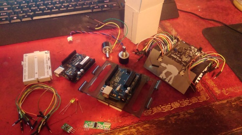
So, first of all, thanks to Coolcomponents for providing an excellent customer service (basically, even if you order one or two components, they deliver within one or two days at a very low extra cost).
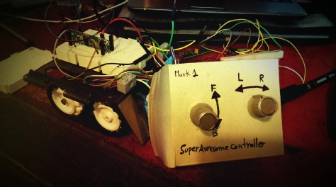
Second, materials. I’m reusing 2 Arduino boards (Duemilanove with chip Atmega 328, and UNO), and the Zumo robot from previous post, plus 2 LEDs, one potentiometer, a few wires, one battery (not in the picture), a small cardboard box, and the RF modules (which I bought from Coolcomponents):
Before starting the main project, let’s do a warm up with a basic example on how to work with these RF modules.
Introduction project.
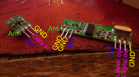
We start by naming the connectors in the RF link modules (spreadsheet for receiver / transmitter). It is good to bend the antenna pins, otherwise when using a breadboard they will be inserted into the breadboard connectors and result in range reduction.
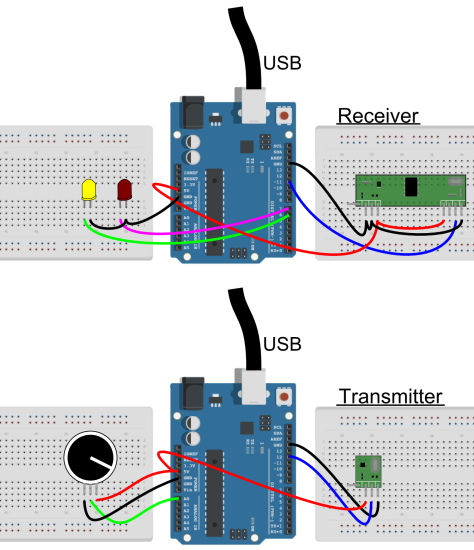
Now for the circuit. We basically read an analog value from the variable resistor on the Duemilanove board, transmit it using the RF transmitter to the RF receiver connected to the UNO board, and light red/yellow LED depending on the value.
The value of the resistor in the potentiometer is not important as we will convert it to a value between 0 and 5V. For the LEDs, as they are standard ones, it is OK to attach them to digital outputs.
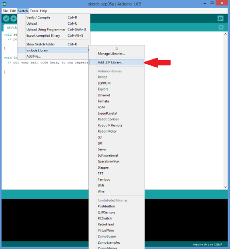
The next step is the code. In order to achieve a good signal (these modules has a lot of noise), we need to get the RadioHead library (Originally it was VirtualWire, but it has been discontinued and now RadioHead is the one being used). You can download the last version, from here. (If you wonder how to connect these circuits to the Arduino, look at the “Detailed description here).
Once you have it, add it to the Arduino IDE.
Once the library is added to the Arduino library list, everything is ready to upload the code. Here it is the code for the transmitter.
// Modified version of ask_transmitter.pde by RadioHead
// -*- mode: C++ -*-
// Simple example of how to use RadioHead to transmit messages
// with a simple ASK transmitter in a very simple way.
// Implements a simplex (one-way) transmitter with an TX-C1 module
#include <RH_ASK.h>
#include <SPI.h> // Not actually used but needed to compile
RH_ASK driver;

void setup()
{
  //LED indicates message sent.
  pinMode(13,OUTPUT);
  Serial.begin(9600);
  //For some reason, this is needed to initialize the driver
  if (!driver.init())
  {
    Serial.println("init failed");
  }
}

void loop()
{
  char msg[4];
  //Read the voltage in the potentiometer.
  float voltage= analogRead(0)* (5.0 / 1023.0);
  //Convert it to string
  dtostrf(voltage,1,1,msg);

  //Send the message and wait to check if it was sent.
  driver.send((uint8_t *)msg, strlen(msg));
  driver.waitPacketSent();

  //Flash LED to indicate message sent.
  digitalWrite(13,1);
  delay(200);
  digitalWrite(13,0);
  delay(200);
}
This is for the receiver.
//  Modified version of ask_receiver.pde by RadioHead
// -*- mode: C++ -*-
// Simple example of how to use RadioHead to receive messages
// with a simple ASK transmitter in a very simple way.
// Implements a simplex (one-way) receiver with an Rx-B1 module
#include <RH_ASK.h>
#include <SPI.h> // Not actualy used but needed to compile
RH_ASK driver;
float Sensor1Data;
char Sensor1CharMsg[4];
void setup()
{
  //LED indicates message sent.
  pinMode(13, OUTPUT);
  Serial.begin(9600); // Debugging only.
  //For some reason, this is needed to initialize the driver.
  if (!driver.init()) {
    Serial.println("init failed");
  }
  //These are for the LEDs
  pinMode(5, OUTPUT);
  pinMode(6, OUTPUT);

}
void loop()
{
  uint8_t buf[RH_ASK_MAX_MESSAGE_LEN];
  uint8_t buflen = sizeof(buf);
  if (driver.recv(buf, &buflen)) // Non-blocking
  {
    int i;
    // Message with a good checksum received, dump it.
    for (i = 0; i < buflen; i++) { // Fill Sensor1CharMsg Char array with corresponding // chars from buffer. Sensor1CharMsg[i] = char(buf[i]); } // Null terminate the char array // This needs to be done otherwise problems will occur // when the incoming messages has less digits than the // one before. Sensor1CharMsg[buflen] = '\0'; // Convert Sensor1CharMsg Char array to integer Sensor1Data = atof(Sensor1CharMsg); //Turn on the corresponding LED if (Sensor1Data > 3) {
      digitalWrite(5, HIGH);
      digitalWrite(6, LOW);
    }
    if (Sensor1Data < 2) {

      digitalWrite(5, LOW);
      digitalWrite(6, HIGH);
    }

    //Flash to indicate message received.
    digitalWrite(13, 1);
    delay(200);
    digitalWrite(13, 0);
    delay(200);
  }
}
And Voilà! With this you are able to light the red or the yellow LED just by adjusting the potentiometer.
This very basic example can be used to transmit a signal form a sensor, to do some wireless projects, or for isntance, to control a device like the ZUMO shield.
RF-link and the ZUMO.
First important thing. The ZUMO shield uses most of the timers in the Arduino board, in particular, the timer1 which is also required for the RadioHead library. So, we need to change the RadioHead library to use timer2. In order to do so, we need to edit the RadioHead library. Simply look for the library and open …Documents\Arduino\libraries\RadioHead\RH_ASK.cpp using a text editor. You need to uncomment //#define RH_ASK_ARDUINO_USE_TIMER2
This line should be also added into your Arduino code for the receiver.
The circuits for the new project can be seen below. Basically, instead of reading one analog value, we are now reading 2, one for forward/backwards control, and the other for turning left/right. The second Arduino just sits on top of the ZUMO shield and uses a couple of wires to connect to the RF receiver.
The code for the new transmitter is
// Modified version of ask_transmitter.pde by RadioHead
// -*- mode: C++ -*-
// Simple example of how to use RadioHead to transmit messages
// with a simple ASK transmitter in a very simple way.
// Implements a simplex (one-way) transmitter with an TX-C1 module
#include <RH_ASK.h>
#include <SPI.h> // Not actually used but needed to compile
RH_ASK driver;

void setup()
{
  //LED indicates message sent.
  pinMode(13, OUTPUT);
  Serial.begin(9600);
  //For some reason, this is needed to initialize the driver.
  if (!driver.init())
  {
    Serial.println("init failed");
  }
}

void loop()
{
  char msg[8];
  //Read the voltage in the potentiometer.
  //This one encodes forward/neutral/backwards
  float voltage1 = analogRead(0) * (5.0 / 1023.0);
  //Read the voltage in the potentiometer.
  //This one encodes left/neutral/rigth
  float voltage2 = analogRead(1) * (5.0 / 1023.0);
  if (voltage1 > 2.6) {
    msg[0] = 'f';
  } else if (voltage1 < 2.4) { msg[0] = 'b'; } else { msg[0] = 'n'; } if (voltage2 > 2.6) {

    msg[1] = 'r';
  } else if (voltage2 < 2.4) {
    msg[1] = 'l';
  }
  else {
    msg[1] = 'n';
  }

  //Send the message and wait to check if it was sent.
  driver.send((uint8_t *)msg, strlen(msg));
  driver.waitPacketSent();

  //Flash LED to indicate message sent.
  digitalWrite(13, 1);
  delay(20);
  digitalWrite(13, 0);
  delay(20);
}
This time, just to make this example more general, we transmit characters. F for forward, b for backwards, n for neutral, l for left and r for right. The code for the receiver is
//  Modified version of ask_receiver.pde by RadioHead
// -*- mode: C++ -*-
// Simple example of how to use RadioHead to receive messages
// with a simple ASK transmitter in a very simple way.
// Implements a simplex (one-way) receiver with an Rx-B1 module
#include <RH_ASK.h>
#include <SPI.h> // Not actualy used but needed to compile
//Enable timmer2 instead of timmer1
#define RH_ASK_ARDUINO_USE_TIMER2
RH_ASK driver(2000, 11, 12, 13, false);;
#include <ZumoMotors.h>
ZumoMotors motors;
float Sensor1Data;
char Sensor1CharMsg[4];
int left_speed, right_speed;
void setup()
{
  //LED indicates message sent.
  pinMode(13, OUTPUT);
  Serial.begin(9600); // Debugging only.
  //For some reason, this is needed to initialize the driver.
  if (!driver.init()) {
    Serial.println("init failed");
  }
}
void loop()
{
  uint8_t buf[RH_ASK_MAX_MESSAGE_LEN];
  uint8_t buflen = sizeof(buf);
  if (driver.recv(buf, &buflen)) // Non-blocking
  {
    int i;
    // Message with a good checksum received, dump it.
    for (i = 0; i < buflen; i++)
    {
      // Fill Sensor1CharMsg Char array with corresponding
      // chars from buffer.
      Sensor1CharMsg[i] = char(buf[i]);
    }
    // Null terminate the char array
    // This needs to be done otherwise problems will occur
    // when the incoming messages has less digits than the
    // one before.
    Sensor1CharMsg[buflen] = '\0';
    // Convert Sensor1CharMsg Char array to integer
    Sensor1Data = atof(Sensor1CharMsg);

    //Choose the correct speeds depending on the command
    if (Sensor1CharMsg[0] == 'f') {
      left_speed = 200;
      right_speed = 200;
    }
    if (Sensor1CharMsg[0] == 'b') {
      left_speed = -200;
      right_speed = -200;
    }
    if (Sensor1CharMsg[0] == 'n') {
      left_speed = 0;
      right_speed = 0;
    }
    if (Sensor1CharMsg[1] == 'l') {
      left_speed = left_speed + 100;
      right_speed = right_speed - 100;
    }
    if (Sensor1CharMsg[1] == 'r') {
      left_speed = left_speed - 100;
      right_speed = right_speed + 100;
    }
    if (Sensor1CharMsg[1] == 'n') {
      left_speed = left_speed;
      right_speed = right_speed;
    }

    //Activate motors
    ZumoMotors::setSpeeds(left_speed, right_speed);

    //Flash to indicate message received.
    digitalWrite(13, 1);
    delay(200);
    digitalWrite(13, 0);
    delay(200);

  }
}
Now it is a matter of uploading the code to the Arduinos and pack things inside the cardboard box…
…and you are ready to have some fun with the ZUMO shield.
Compared with the XBee the range is not great, but these modules are by far cheaper than the XBee, and they can be improved by adding antennas.
Today I’m going to show you how to control the Zumo remotely from the computer using an Arduino UNO board and two Xbee. Basically, it’s the continuation of my previous tutorial:
this time the Arduino will be driving the Zumo instead of lightning LEDs.
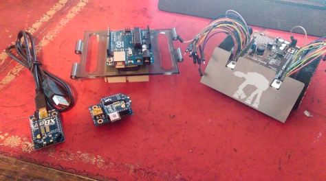
Materials:
Breadboard
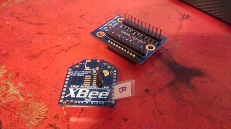
2 XBee with USB adaptor
Arduino UNO
Zumo Robot
Few wires for connections
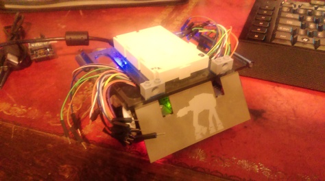
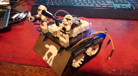
As you can see, I already have done 2 modifications. One of them is that I soldered the wires to the Zumo in order to have connection with my all my Arduino pins. The other modification is that my breadboard is glued on the back of the Arduino.
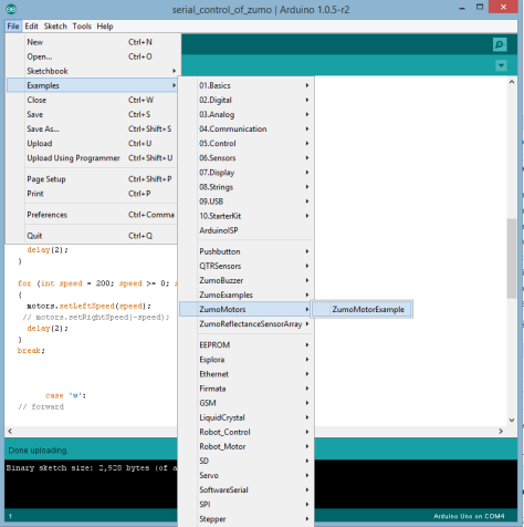
Step 1. Install Zumo libraries on Arduino IDE. You are going to need these libraries in order to send commands to the Zumo shield. Go to Zumo-shield on GitHub and on the rigth hand side, download as a zip. Once you have that file, decompress it, and move each library folder (Pushbutton, QTRSensors, ZumoBuzzer, ZumoExamples, ZumoMotors, and ZumoReflectanceSensorArray) into the “libraries” subdirectory inside your Arduino sketchbook directory. You can view your sketchbook location by selecting File→Preferences in the Arduino environment; if there is not already a “libraries” folder in that location, you should create it yourself. After installing the library, restart the Arduino environment so it can find the Zumo Shield libraries and their examples. You will know that it is properly installed because it will show in the IDE Examples like this:
Step 2. Write code to drive Zumo from serial. Basically, we are going to modify the “ZumoMotor Example” to run the motors for a short period of time when a string is send through the serial port.
#include <SoftwareSerial.h>
#define Rx    4
#define Tx    5
SoftwareSerial Xbee (Rx, Tx);
#include <ZumoMotors.h>
//This script will control the Zumo motors by reading strings through the serial port.
// a w s d will control left forward bakwards and right
ZumoMotors motors;
int inByte = 0;         // incoming serial byte
int speedr = 0;         //speed of left engine
int speedl = 0;         //speed of rigth engine
void setup()
{
   Serial.begin(9600);
    Xbee.begin(9600);
}
void loop(){
  //This will speed down the engine unless a command to speed up is received
  if(abs(speedr)>0){speedr=speedr-speedr/5;}
  if(abs(speedl)>0){speedl=speedl-speedl/5;}
  motors.setRightSpeed(speedr);
  motors.setLeftSpeed(speedl);
  //If a command is received through the serial and it is a driving comand,
  //then it speeds up or down the corresponding engine
  if (Serial.available() > 0){
    inByte = Serial.read();
    switch(inByte){
      case 'a':// turn left
        speedr=speedr+400;
        break;
     case 'd': // turn right
        speedl=speedl+400;
        break;
     case 'w': // forward
        speedr=speedr+400;
        speedl=speedl+400;
        break;
     case 's':// backward
        speedr=speedr-400;
        speedl=speedl-400;
        break;
      }
  }
  if (Xbee.available() > 0){
    inByte = Xbee.read();
    switch(inByte){
      case 'a':// turn left
        speedr=speedr+400;
        break;
     case 'd': // turn right
        speedl=speedl+400;
        break;
     case 'w': // forward
        speedr=speedr+400;
        speedl=speedl+400;
        break;
     case 's':// backward
        speedr=speedr-400;
        speedl=speedl-400;
        break;
      }
  }
  delay(5);
}
To test how it works, simply put the Arduino on top of the Zumo shield and load the code into it. Without disconnecting the USB, turn the Zumo on and the open the serial port on the Arduino IDE.
You migth notice the reference in the code to the XBee. We are going to use the XBee connected as in our previous tutorial (XBee 002: radio-chat between PC and Arduino) the only change is that here we have pins 4 and 5 free (check Zumo shield pins usage here).
Step 3. Write Python code to read Keyboard and print to serial port. First, we need to install pygame, which is a set of libraries and functions designed to program games…. and they are very handy for reading the keyboard.
First, go to the pygame downloads webpage and look for the installation file that match your system and Python version. For me it works
Simply run it and it will be installed. Now the code for Python, which is very simple:
import sys, serial, pygame, time
pygame.init()
size= width, height = 60,40
#The next command creates a window,
#everytime you are on that window and press a key
# in the leyboard, it will be analysed and
#if it is one of the driving commands, it will be send
#through the serial port.
screen = pygame.display.set_mode(size)
screen.fill((0,0,0))
ser=serial.Serial('COM7',9600,timeout=1)
key=''
while 1:
    events = pygame.event.get()
    for event in events:
        #This is just to quit
        if event.type == pygame.QUIT:
            sys.exit()
        if event.type == pygame.KEYDOWN:
            key=event.key
        if event.type == pygame.KEYUP:
            key=''
#The command is being send through the serial until we release the key
#Because we have a loop in the arduino and only checks the serial port every
#5 ms, by adding here a 10ms delay we make sure robot follows the orders in real time
    time.sleep(0.01)
    if key == 97:
        ser.write('a')
    elif key == 115:
        ser.write('s')
    elif key == 119:
        ser.write('w')
    elif key == 100:
        ser.write('d')
Step 4. Connect XBee, and enjoy (use same connection diagram for the XBee as in XBee 002: radio-chat between PC and Arduino but changing 6 and 7 pins for 4 and 5.). Our XBee is ready from the previous tutorial, and our code already includes reading XBee or USB… so everything is ready.
By the way… you might ask why I have 2 Lego bricks on the top… it is for this
We will have an Arduino board connected by USB to one computer and by radio (using a pair of XBee) to another computer. Using one computer or the other we are going to switch LED on and off.
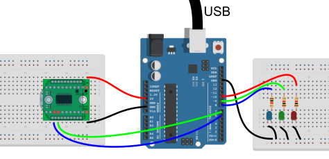
Step 1. Make the electrical connections. We connect 3 LED to pins 9,9,10 on the Arduino. Remember to use an appropriate resistor to limit the amount of current. Use the ground on the Arduino to close the circuit.
To be able to communicate with the XBee you need to power it (+5V to pin VDD and ground to VSS pin), the Arduino can provide enough power, so use it. Connect pin 7 to DIN and pin 6 to DOUT. These two pins are going to be used for serial communication between the Arduino and the XBee.
For other alternatives to communicate between a microcontroler and the XBee, the parallax webpage gives a good support here.
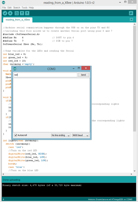
Step 2. The code. As you can see, the code comments explain what it does. Simply reads from Serial (USB) or from the new serial defined in ports 6 and 7 to comunicate with the XBee. Depending on what we read from the Serial, we turn on one LED or other.
//Arduino serial comunication happens through the USB or on the pins TX and RX
//including this file allows us to create another Serial port using pins 6 and 7
#include <SoftwareSerial.h>
#define Rx    6                // DOUT to pin 6
#define Tx    7                // DIN to pin 7
SoftwareSerial Xbee (Rx, Tx);

//Some variables for the LEDs and reading the Serial
int blue_led = 8;
int green_led = 9;
int red_led = 10;
char incoming ='empty';

void setup(){
  Serial.begin(9600);  // start serial port at 9600 bps:
  Xbee.begin(9600);
  pinMode(red_led, OUTPUT);
  pinMode(blue_led, OUTPUT);
  pinMode(green_led, OUTPUT);
}

void loop(){
  if(Serial.available()){
    //If there is data on the Serial port, read it and ligth the corresponding lights
    incoming = Serial.read();
    lights (incoming);
  }
  if(Xbee.available()){
    //If there is data on the XBeeSerial port, read it and ligth the corresponding lights
    incoming = Xbee.read();
    lights (incoming);
  }
}

int lights(char incoming){
  switch (incoming){
    case 'red':
    //Turn on the red LED
    digitalWrite(red_led, HIGH);
    digitalWrite(blue_led, LOW);
    digitalWrite(green_led, LOW);
    break;
    case 'blue':
    //Turn on the blue LED
    digitalWrite(red_led,LOW );
    digitalWrite(blue_led, HIGH);
    digitalWrite(green_led, LOW);
    break;
    case 'green':
     //Turn on the green LED
     digitalWrite(red_led, LOW);
     digitalWrite(blue_led, LOW);
     digitalWrite(green_led, HIGH);
     break;
     default :
     // default is optional
     break;

  }
}
Upload the code to your Arduino.
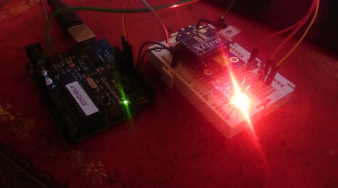
Setp 3. Communicate There is 2 ways of communication. First, using the same computer that is already connected by USB with the Arduino, open the Serial Monitor in the Arduino UI and write the colour of the LED you want to be on.
And the LED turns on.
As you can see my electrical set-up is not as tidy as the schematic… but it works.
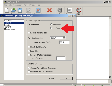
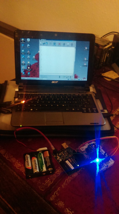
The second option is using the other XBee (from our previous tutorial) and the program CoolTerm to send data through the XBee. So, disconnect the USB from the Arduino and power it with batteries (or use one computer to power and another to communicate). Connect the “A” XBee with its USB adaptor to the computer and open CoolTerm program. The only change you need to do respect to the previous tutorial is enabling Line mode under Options>Terminal. This will enable sending one string at a time instead of individual characters.
Once this is done… it is ready for communication. Simply write the name of the colour you want.
Hope you find it useful… please, practise it if you can, because soon we are going to use this hack with something more funnier…


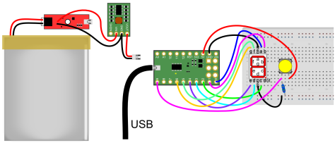 On the other side of the circuit, the A-Star is connected to the 7 segment LED (connect ground and 6 digital pins and pay attention to the order of the connections). The last thing to connect is the push-button. The button is connected to 5V in one side and to digital pin 9 and through a resistor to ground in the other side. In this way, every time we push the button pin 9 goes to 5V (without draining too much current) and when released, pin 9 goes back to GND.
 Simply power the RF receiver and connect the first data line to pin 11. As an extra, you can add a wire to the antenna, for 434 MHz 16.5 cm wire will do it ok as a quarter wavelength antena.
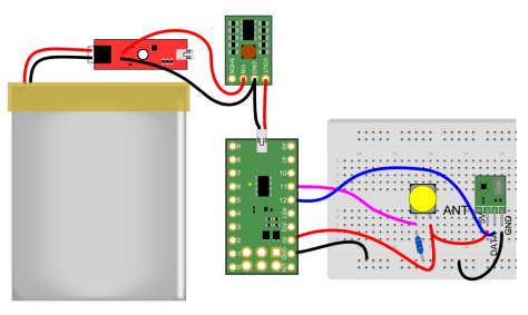 Basically it is the S-Star connected to a button, the emitter, and powered by the battery.