Today I’m building a light for my bike’s wheel. This light will be attached to the wheel and will shine on and off as the wheel spins in order to create a stand still image.
Usually I build things just buying electronics and putting them together, but for this one I need an extra step, design and fabrication of a plastic box to attach the light to the wheel. Because of this extra step, I though this was a nice opportunity to try 4 Delta 3D printing training course.

Although I have used 3D printing before (see for instance my light stand or how I fixed an old game), I lack most of the good practice in 3D printing knowledge, and the 4 Delta course covers that perfectly.
The course is completely on-line with videos and e-books. It took me about one week working only half an hour or less everyday. Within the course, you learn how to properly design pieces, the materials available, how to set-up your 3D printer, common design mistakes, how to export models, printing errors… and you get access to Onshape (CAD software that runs on your browser). And if it was not enough, for your cash… you get permanent access to the new 4 Delta forum where you can ask and solve questions about DIY 3D printing. Resuming, it is a very good investment in yourself and your future projects.
So… I took the course and used Onshape to design my box.
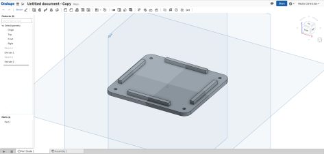
It was composed of 3 parts.
And it includes holes for attaching the parts together with screws.
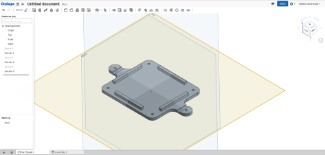
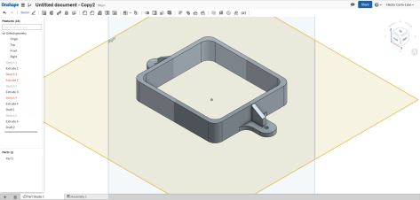
The idea is that the last piece and the middle one will grip on the wheel radios fixing the box in place. However, although this design is made in order to make 3D printing easy, it has some defects that can be improved. For instance, walls of the middle part are too thick and don’t include wholes for connecting USB, there is no holes for attaching the lights or the electronics, the box should be able to attach/detach from the bike without having to open them completely (this feature will need a major review), and there is no mounting for the Hall sensor that will determine the angular position.
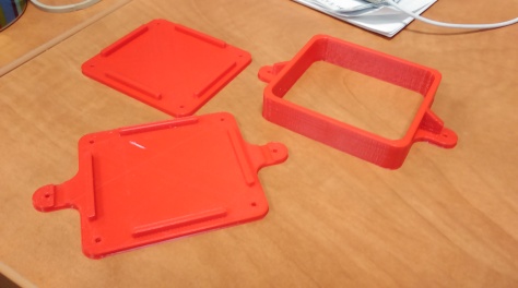
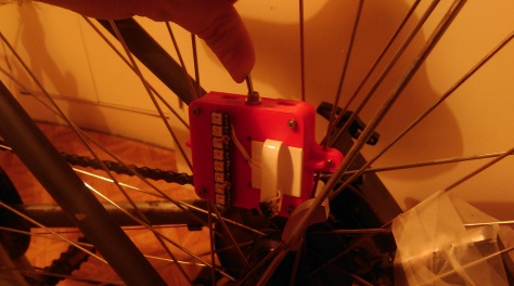
However, for a Mark 1 model the design is good enough and this is how it looks like once 3D printed (I used 4Delta printers through the 3D HUBS).
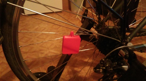
and this how it goes on my bike (I have a stand to workout at home during winter).
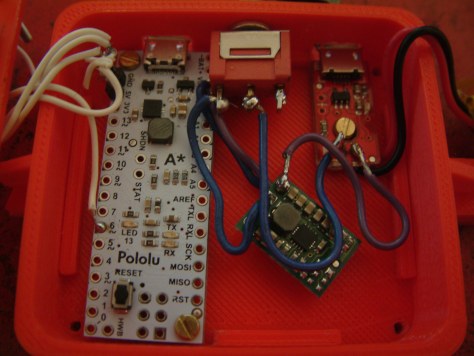
Now lets go for the electronics.
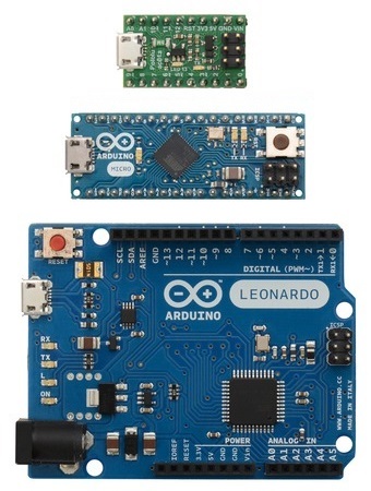
Recently I have used a very nice A-Star micro board (because it is extremely tiny). For this project I will be used the bigger version, the A-Star micro. Why going for the A-Star instead of one of the more common and better supported Arduino boards? My main reason is because they do the A-Star micro and hell, that board is really tinny. By using more boards from the same company, I will be able to learn more and improve my designs even further.
This is my shopping list in Coolcomponents:

- A-Star 32U4 Mini ULV (can operate using voltage in the range 0.5 V to 5.5 V so it can be powered with a 3.7V LiPo battery).
- NeoPixel Stick – 8 RGB LEDs.
- Lithium Polymer Battery.
- LiPo Charger – Micro-USB.
- 5V Step-Up/Step-Down Voltage Regulator (not necessary with this board, but I want to keep the design as flexible as possible).
- Linear Hall sensor (this one in particular is quite expensive and not all its features are used here, but I found that it is a quite good sensor so I keep using it as much as I can).
- Neodymium magnet (I use an old one from a hard drive, but any magnet can do)
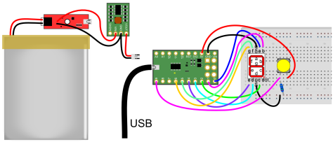
The circuit diagram for this set-up is quite simple. Note: If using more NeoPixel sticks, they can be attached in series one after the other.
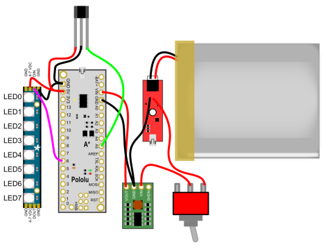
The circuit diagram is a battery attached to a micro-USB for charging. The output of the battery is attached to an interrupter which output goes to the voltage regulator. The voltage regulator powers the A-Star. The A-Star powers both the Hall sensor and the NeoPixel LED strip. The output of the Hall sensor is connected to the analogue pin A5 (pin 23) and the input of the NeoPixel is attached to pin 6.
Now lets go for the code, but before explaining the code, 2 things. The first one is that in order to run the NeoPixel, you need to download the zip file with the libraries and install it in the Arduino IDE (simply Sketch>Include Library>Add .ZIP Library). The second thing is about how to draw things. For my example I’m going to use a red heart. The idea is that the shape we want to draw is divided into columns, each one of 8 rows. As the wheel spins the LEDs will cycle through the columns. So we can turn our draw into an array and know exactly which pixel has to be on and when. In addition, as the NeoPixel LEDs are numbered we need to convert the array into a vector and cycle through the vector.
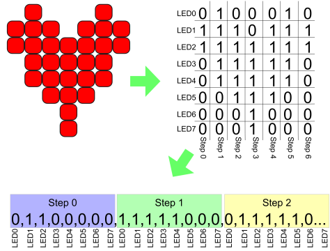
Keeping this in mind, this is the code I prepared. Basically, it reads the Hall sensor and when the signal from the sensor deviates from the average it means the sensor has passed over the magnet and a turn of the wheel has happened. With this trick we can measure the period of a revolution and hence synchronize the lighting of LEDs. The next thing that the code does is light the LEDs according tot he pattern (see heart shaped pattern above), the time it takes to jump from one step to another depends on the speed of the wheel (right now it is set to take about 1 degree).
#include <Adafruit_NeoPixel.h>
#ifdef __AVR__
#include <avr/power.h>
#endif

// Which pin on the Arduino is connected to the NeoPixels?
#define PIN            6

// How many NeoPixels are attached to the Arduino?
#define NUMPIXELS      8
//This is to define the shape we want to draw (Note: monocolor at the moment).
int pixi[] = {0, 1, 1, 0, 0, 0, 0, 0, 1, 1, 1, 1, 1, 0, 0, 0, 0, 1, 1, 1, 1, 1, 0, 0, 0, 0, 1, 1, 1, 1, 1, 1, 0, 1, 1, 1, 1, 1, 0, 0, 1, 1, 1, 1, 1, 0, 0, 0, 0, 1, 1, 0, 0, 0, 0, 0,0,0,0,0,0,0,0,0};
//This defines the number of steps it takes to draw the full image
int numsteps = 7;

//This is to measure position using the Hall sensor
#define numReadings 20
float readings[numReadings];
float sensorval;
float average = 0;
int start;
int finished;

// When we setup the NeoPixel library, we tell it how many pixels, and which pin to use to send signals.
// Note that for older NeoPixel strips you might need to change the third parameter--see the strandtest
// example for more information on possible values.
Adafruit_NeoPixel pixels = Adafruit_NeoPixel(NUMPIXELS, PIN, NEO_GRB + NEO_KHZ800);

void setup() {
  pixels.begin(); // This initializes the NeoPixel library.
  start = millis(); //This initialices the function to meassure the wheel speed.
}

void loop() {
//Hall sensor is attached to pin 23
//We read the output each iteration (Powering the sensor with 5V the output is 2.5V at zero magnetic field and 0V/5V at negaqtive/positive saturation.
//At the moment we don't need to convert the reading from 1024 bits into a real voltage reading.
  sensorval = analogRead(23);
//We keep the last 20 values in memory by sifting values in an array
//and simply deleting the oldest one and adding the new one at the beguining
//To save time the average is calculated at the same time
  average = readings[numReadings-1];
  for (int k = 1; k < numReadings; k++)   {     readings[numReadings - k] = readings[numReadings - 1 - k];     average = average + readings[numReadings - k];   }   average = average / numReadings;   readings[0] = sensorval;   //Now, if the new reading deviates too much from the average (standard deviation can be calculated,    //but symply by using a fixed interval works fine), then it means the wheel has completed a cycle and it is time to draw again the symbol.   //We can use the elapsed time to calculate the spinning speed. //An artificial delay can be included here to select in which part of the cycle we want to draw.   if (sensorval > average + 20 or sensorval < average - 20)
  {
    finished = millis();
float milisperangle = abs(finished - start) / 360;
start = millis();
delay(milisperangle*8);
draw(3*milisperangle);
  }
}

void draw(int delayval)
{
  //This function takes numteps x delayval (ms) to execute
  //For a set of NeoPixels the first NeoPixel is 0, second is 1, all the way up to the count of pixels minus one.
  for (int j = 0; j < numsteps; j++) {
    for (int i = 0; i < NUMPIXELS; i++) {
      // pixels.Color takes RGB values, from 0,0,0 up to 255,255,255
      //Now we only use red color
      pixels.setPixelColor(i, pixels.Color(255 * pixi[i + j * NUMPIXELS], 0, 0)); // Moderately bright green color.
    }
    pixels.show(); // This sends the updated pixel color to the hardware.
    delay(delayval); // Delay for a period of time (in milliseconds).
  }
}
Remember that depending on which side of the wheel you place the lights the spinning is the same as you write or the opposite and you need to change the steps accordingly.
The next step is placing the components inside of the box (I added some extra wholes). Some of the wholes could have been done in the designing part, but I didn’t though too much in the final details, also, some of the wholes is better to do them afterwards in order to have a good print.
The battery goes on top and the box closes gripping to the wheel.
As I said, I didn’t include a support for the Hall sensor, so I added a last-minute solution which also allows me to change the distance between the sensor and the magnet (the thing close to the sensor in the next picture).
And Voilá!

That’s all!
.
.
.
.
.
.
.
Ok ok. Here it is, a tribute to 4 Delta for their help with the training and the 3D printing…
.
.
.
.
.
.
Want even more?!
As an extra, here it is a close look at the NeoPixels.
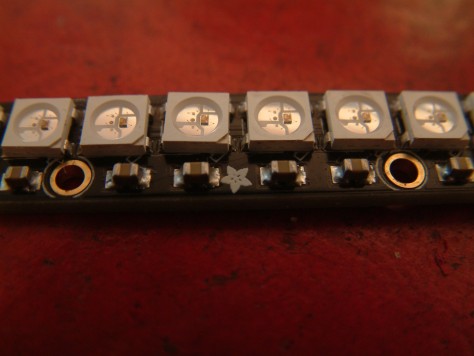
Hope you like it!

 On the other side of the circuit, the A-Star is connected to the 7 segment LED (connect ground and 6 digital pins and pay attention to the order of the connections). The last thing to connect is the push-button. The button is connected to 5V in one side and to digital pin 9 and through a resistor to ground in the other side. In this way, every time we push the button pin 9 goes to 5V (without draining too much current) and when released, pin 9 goes back to GND.
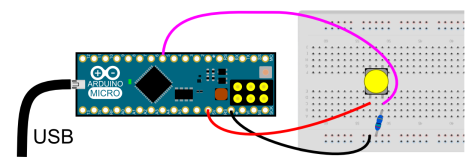
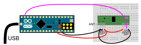 Simply power the RF receiver and connect the first data line to pin 11. As an extra, you can add a wire to the antenna, for 434 MHz 16.5 cm wire will do it ok as a quarter wavelength antena.
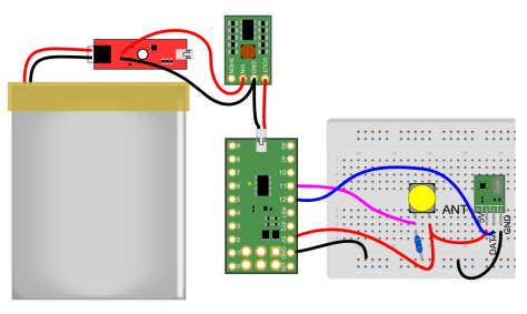 Basically it is the S-Star connected to a button, the emitter, and powered by the battery.